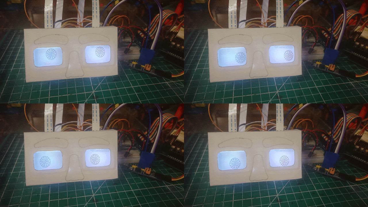
The head will be coming soon, but before I start on the head I want to design something for the eyes.
I have an idea, but want to test it out first.
I want to make the eyes out of the cheap
Nokia screens available on eBay.
There are two types, one comes attached to a breakout board and the LPH7366
that does not.
The LPH7366 has a zebra ribbon connection, it also has nine pins internally
connected to this ribbon.
I intend to use the LPH7366 version, they are cheaper (I don't think people
know how to connect them), also I want to make a board specially for this
project.
I am going to design a board that takes two of these screens and will control
them from an
PCF8574 I2C device, so that I can control it through my I2C bus on my robot.
When I design the eyes I want to give them colour.
I have ordered some WS2812B Adressable RGB LED's
to do this.
When I get them I will add them to my prototype.
I have also written an Arduino library so others can use it once I have
finished it.
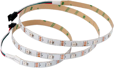
Got some WS2812B Addressable LEDs.
I cut two sections from the strip and stuck them on a new prototype support.
I wanted to control the WS2812B Addressable LEDs through the PCF8574 I2C device also.
But I was not able to do this. The signal to the WS2812B has a pulse width of 400 nanoseconds.
That's 400 billionth of one second, the PCF8574 is not fast enough to do the
switching at this speed.
This is not really an issue, it just means there is one extra wire for the
WS2812B LEDs and if I add more WS2812B LEDs, I can just add them to this wire.
It's not what I wanted to do so I had another look on the web and found some
other Addressable LEDs. SK9822, these work similar to the Nokia Screens so I have ordered 10 of these.
These have clock and data wires (2 wire).
These are just what I wanted, because they have a clock wire, I am able to
control them with the PCF8574 module, I am able to use the same clock wire I
am using for the Nokia Screens, the data wire is a separate one.
(In hindsight I think I could have used the Nokia data wire also, but I had a
touch of tunnel vision at the time and I have now ordered the BCBs.)
I made myself a small PCB for each Eye to mount them on, also attached wires to connect them to the main PCB which I will get made out.
I made myself a small PCB for each Eye to mount them on, also attached wires to connect them to the main PCB which I will get made out.
I would have had the PCB made out with the main PCB, but the cost would
double.
The offer manufacturers do for small prototyping boards, is only for single
PCBs.
This is not a hard PCB to make.
This is not a hard PCB to make.
I made an other prototype support to hold them, the back now looks like this:
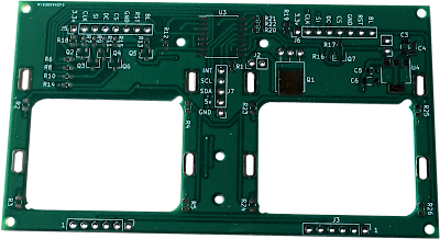
I designed the main PCB using KiCAD.
The Circuit:
I have tried to make the board so it can be used in a variety of ways.
- It will be possible to use the board with only the Nokia screens attached with a couple of capacitors and headers. With this setup, it can be connected to a microprocessor via the SPI (3.3v only).
- If you just want to light the screen the normal way it was on the phones. Eight LEDs and resistors can be added to the above setup.
- If you want to control every thing through I2C, then most of the components on the back are needed.
- I have also put provision for an axillary switched output. I am thinking of making razing eyebrow's :)
I am having the board made at 
and will add a link to a shared post there when done, if anyone wants to make one.

and will add a link to a shared post there when done, if anyone wants to make one.
Received the PCBs:
This was easaly fixed, I just had to cut a little bit of copper track.
I think I also made the gaps too small between the contacts of the Nokia
Screens, I was able to widen them.
For some reason it didn't work first off, it took me a few days to find what
was wrong.
I had forgot I had made some changes to which pins on the PCF8574 did what.
I eventually realised I had swopped two over, once I altered this in the
code all worked perfectly.
I have corrected my files for making the PCB also.
If you want to make one of these, I have shared it at
PCBWay.
Rear view:
As I am not using the four little diodes around each screen, the resistors:
R2, R3, R4, R5, R23, R24, R25 and R26 are not fitted. Also not fitted are
the SPI headers.
I have done a blog on how I design a PCB with a short video of me fitting
SMDs here:
DC Motor Driver X6.
Front view:
This side just needs the two capacitors and screens, the header from the
3.3v regulator is also not fitted.
As the Screens are designed for a thinner PCB, I don't advise trying to push
the clips of the screens all the way through the PCB.
I used UV resin to hold the screens in place.
Once I have the screen set correctly.
I put a few drops on the back and shine the UV light on it before it has
chance to run all the way to the front.
The UV resin I use is the
cheap stuff from eBay.
I think its a week version of the finger nail resin, I find if you use too
little amount, it does not have a mass to start the hardening reaction.
Because I have made some changes to the PCB, I have decided to change the
cables on the RGB LEDs.
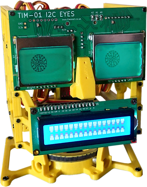
Eyes Fitted to the head:
I have done an Arduino Library to control the Eyes via I2C.
The Head is continued here:
TIM-01_Head.
Should anyone decide to make this, don't hesitate in asking for help.
I found that some of the Nokia Screens can be temperamental lining them up with the connections on the board.
I think these screens are old stock. In one order of three I received three different revisions of the screens, each having slight differences in the manufacturing.
I think this is why these versions of the screen are not sold on breakout boards.


No comments:
Post a Comment